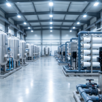
A commercial reverse osmosis system that isn’t maintained will fail quietly — TDS creep, pressure loss, and membrane fouling happen gradually until the system is producing water that’s no longer meeting specs. The good news is that a well-maintained RO system lasts 10–15 years with predictable component replacement on a schedule. This guide covers what needs to be done, when, and the warning signs that something is wrong before it becomes an expensive problem.
Commercial RO Maintenance Schedule
| Interval | Task | Why |
|---|---|---|
| Monthly | Log feed TDS, permeate TDS, concentrate TDS, feed pressure, permeate flow rate, concentrate flow rate | Baseline trending. A 10–15% drop in permeate flow or a 10–15% rise in salt passage (permeate TDS) signals fouling before it becomes critical. |
| Quarterly | Inspect and replace pre-filters (sediment, carbon block) | Clogged pre-filters starve the high-pressure pump of flow, causing cavitation and premature pump failure. Replace on schedule — don’t wait for a pressure drop alarm. |
| Quarterly | Check O-rings, fittings, and vessel end caps for weeping | Minor O-ring weeping causes bypass of untreated water into permeate. Visual inspection takes 5 minutes. |
| Annually | Normalize membrane performance against baseline | Calculate normalized permeate flow and normalized salt rejection using temperature-corrected data. Normalized values strip out seasonal water temperature variation to show true membrane condition. |
| Annually | Clean-in-place (CIP) membrane cleaning if performance has declined 10% | Fouling is reversible if caught early. CIP with appropriate chemistry (alkaline wash for organics/biofilm, acid wash for scale) can restore 80–95% of lost performance. |
| 2–5 years | Replace RO membranes | Membrane lifespan depends on feed water quality and operating conditions. Municipal water with proper pre-treatment: 3–5 years. Industrial or well water with variable quality: 2–4 years. |
| 3–7 years | Inspect high-pressure pump seals and impellers | Pump seal failure is the most common mechanical failure in commercial RO systems. Seal replacement is inexpensive; a failed seal that damages the pump is not. |
Pre-Filter Maintenance: The Most Common Overlooked Task
The single most common cause of preventable commercial RO failure is a neglected pre-filter. Pre-filters — typically a 5-micron sediment cartridge followed by a carbon block for municipal water — protect the high-pressure pump and RO membranes from particulate and chlorine. When they’re ignored:
- Sediment filter clogging reduces feed pressure below the minimum required for membrane operation. The high-pressure pump cavitates, accelerating seal and impeller wear.
- Carbon block exhaustion allows chlorine breakthrough to the RO membrane. Even 0.1 ppm continuous chlorine exposure degrades thin-film composite membranes. A carbon block that’s been running 9 months on chlorinated municipal water may be passing chlorine long before it shows a pressure drop.
Pre-filters should be replaced on a schedule — every 3 months on a commercial system, or based on differential pressure measurement (replace when the pressure drop across the pre-filter housing exceeds 10–15 PSI). Don’t judge a carbon block by its appearance; exhausted carbon looks identical to fresh carbon.
Recognizing RO Membrane Fouling: 4 Types
1. Scaling (Mineral Fouling)
Symptoms: Gradual increase in normalized pressure drop across the membrane, gradual decrease in normalized permeate flow. TDS rejection may remain acceptable until late-stage scaling.
Cause: Calcium carbonate, calcium sulfate, silica, or barium sulfate precipitation on the membrane surface. Occurs when concentration polarization pushes sparingly soluble salts above their saturation limits at the membrane wall.
Prevention: Antiscalant dosing at the correct rate for feed water chemistry. Scale prevention requires knowing your feed water mineral profile — test annually and adjust antiscalant dosing as supply changes.
Treatment: Acid CIP wash (citric acid or hydrochloric acid at low concentration). Effective if caught before scale hardens to a crystalline structure; late-stage calcium carbonate scale may be irreversible.
2. Biological Fouling (Biofouling)
Symptoms: Increased pressure drop across membranes, reduced flow, possible increase in salt passage. Biofouling often produces a “rotten egg” or musty odor in permeate.
Cause: Bacteria form a biofilm on the membrane surface and feed spacers. Common in systems with intermittent operation (bacteria grow during shutdown), municipal water with low chlorine residual reaching the membranes, or warm feed water temperatures (25°C).
Prevention: Shock disinfection during commissioning and after extended shutdown. Maintain chlorine pre-treatment (then remove before the membrane). Avoid long idle periods — keep the system in continuous or minimum-run mode.
Treatment: Alkaline CIP wash (sodium hydroxide + surfactant). Chloramine disinfection for severe biofouling. Note: chlorine itself damages TFC membranes — use only chloramine-safe biocides or non-oxidizing biocides rated for membrane use.
3. Colloidal / Particulate Fouling
Symptoms: Rapid increase in feed-side pressure drop (beginning of the membrane train). Permeate TDS may remain acceptable while flow drops.
Cause: Fine particulate matter — silts, colloids, iron oxides — passing through pre-filters and depositing on the membrane surface. Silt Density Index (SDI) of feed water above 3 indicates high colloidal fouling potential; above 5 is unacceptable for direct RO operation.
Prevention: Proper pre-treatment: ultrafiltration (UF) pre-stage for surface water or well water with high SDI, coagulation-filtration for high turbidity sources.
Treatment: Alkaline CIP wash (sodium hydroxide) loosens organic colloids. May also respond to EDTA chelation for iron-based fouling.
4. Organic Fouling
Symptoms: Pressure drop increase similar to biofouling but without biological odor. Common in systems treating surface water or water with high natural organic matter (NOM).
Cause: Humic acids, tannins, and other dissolved organics adsorb onto the membrane surface.
Treatment: Alkaline CIP wash at pH 11–12. Sodium hypochlorite soak (for membranes rated for chlorine exposure — most TFC membranes are not; check specifications).
Clean-in-Place (CIP) Procedure Overview
CIP should be performed when normalized permeate flow has declined 10% or normalized salt passage has increased 10% from baseline. The procedure:
- Prepare cleaning solution in a clean tank — typical volumes: 10–50 gallons depending on system size
- Recirculate cleaning solution through the membrane train at low pressure (60–100 PSI) and high flow rate for 60–90 minutes
- Soak period: 1–4 hours at reduced flow
- Rinse with clean feed water until permeate is neutral pH and free of cleaning agent
- Return to service and log normalized performance to verify improvement
Always match cleaning chemistry to the foulant. For unknown fouling, run alkaline wash first (removes organics and biofouling), then acid wash (removes scale). Combining both in the wrong order can set scale more permanently.
Performance Trending: The Data You Need to Catch Problems Early
Most RO membrane problems are preventable if you’re logging performance data and trending it over time. The minimum dataset:
| Measurement | Instrument | Trend to Watch |
|---|---|---|
| Feed TDS (ppm) | Inline TDS meter or conductivity sensor | Baseline for rejection calculations |
| Permeate TDS (ppm) | Inline TDS meter on permeate line | Rising TDS = membrane damage or O-ring bypass |
| Feed pressure (PSI) | Pressure gauge before membranes | Declining pressure = pre-filter clogging, pump wear |
| Permeate flow rate (GPD or GPM) | Flowmeter on permeate line | Declining flow = fouling |
| Concentrate flow rate (GPD or GPM) | Flowmeter on reject line | Used to calculate recovery rate |
| Feed water temperature (°F) | Thermometer on feed line | Required for normalization calculations — flow changes 3% per °F |
RO System Troubleshooting Quick Reference
| Symptom | Most Likely Cause | First Action |
|---|---|---|
| Low permeate flow, normal TDS rejection | Fouling (scaling or colloidal), clogged pre-filter | Check/replace pre-filter; log normalized flow vs. baseline |
| High permeate TDS (poor rejection) | Membrane damage, O-ring failure, bypass | Individual element testing to locate failure; inspect O-rings |
| Both low flow and high TDS | Severe biofouling or advanced scaling | CIP; evaluate replacement if CIP doesn’t restore performance |
| Rapid pre-filter pressure drop | High SDI feed water, turbidity spike | Check feed water turbidity; consider UF pre-stage |
| Musty or sulfur odor in permeate | Biofouling in membranes or storage tank | Shock disinfect system; CIP with alkaline/biocide wash |
| System won’t reach operating pressure | Pump wear, pre-filter clogging, feed pressure low | Check inlet pressure, pre-filter differential pressure, pump output |
| Permeate TDS suddenly spikes | O-ring failure, membrane puncture, interconnector damage | Element-by-element conductivity test to isolate; inspect vessel end caps |
AMPAC USA Service and Support
AMPAC USA commercial RO systems are manufactured in the United States and backed by direct technical support from the engineering team that designed the system. We stock replacement membranes (FILMTEC™ elements), pre-filter cartridges, high-pressure pump seals, and O-ring kits for all AMPAC USA systems — no wait on overseas parts.
For systems experiencing performance decline, our technical team can walk operators through normalized performance analysis and cleaning procedures via phone or email. For systems requiring field service in Southern California, on-site support is available.
Experiencing RO system performance issues? Contact our technical team with your feed TDS, permeate TDS, operating pressure, and permeate flow rate — we can usually identify the cause and recommend action within one business day.
Related: Commercial RO System Sizing Guide | RO Water Quality: TDS, pH, and Conductivity Guide | Commercial RO Systems
Related Articles
- AMPAC USA Commercial RO System Specifications: APRO300 to APRO6000 | AMPAC USA
- How to Choose a Commercial RO System: Complete Buyer's Guide | AMPAC USA
- RO Recovery Rate Explained: What It Is, What Limits It, and How to Optimize | AMPAC USA
- RO Membrane Types: BW30, SW30, High-Rejection & Fouling-Resistant | AMPAC USA
Frequently Asked Questions
How often should commercial RO pre-filters be replaced?
Every 3 months on a commercial system, or based on differential pressure measurement, replacing when the pressure drop across the pre-filter housing exceeds 10-15 PSI. A neglected pre-filter is the single most common cause of preventable commercial RO failure.
What are the four types of RO membrane fouling?
Scaling (mineral precipitation like calcium carbonate), biological fouling (bacterial biofilm), colloidal/particulate fouling (fine silts and iron oxides), and organic fouling (humic acids and dissolved organics). Each requires a different cleaning chemistry to reverse.
When should a commercial RO system undergo CIP cleaning?
When normalized permeate flow has declined 10 percent or normalized salt passage has increased 10 percent from baseline. For unknown fouling, run an alkaline wash first to remove organics and biofilm, then an acid wash for scale.
How long does a well-maintained commercial RO system last?
10-15 years overall, with membranes typically replaced every 2-5 years depending on feed water quality, and pump seals or impellers inspected every 3-7 years.