
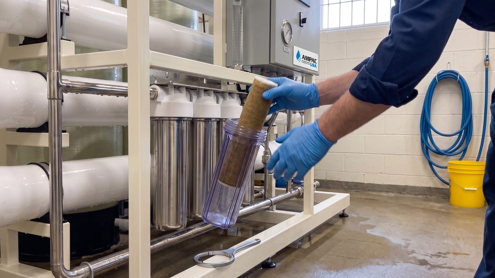

Industrial RO systems are workhorses. They run continuously, handle variable feed water quality, and are expected to hit rejection rates north of 95% day after day. When something goes wrong, the symptoms can look similar even when the underlying causes are completely different – low output could be a fouled membrane, a failing pump, or just a clogged sediment filter. This guide walks through the 12 most common problems, with measurable diagnostic thresholds and specific corrective steps for each.
| Parameter | Small Systems (<10 GPM) | Mid-Size (10-100 GPM) | Large (>100 GPM) |
|---|---|---|---|
| Feed Pressure | 60-80 psi | 100-150 psi | 150-250 psi |
| Recovery Rate | 50-60% | 65-75% | 75-85% |
| Salt Rejection | ≥95% | ≥97% | ≥98% |
| Permeate TDS (municipal feed) | <50 ppm | <30 ppm | <20 ppm |
| Differential Pressure (per element) | <15 psi | <12 psi | <10 psi |
| Concentrate-to-Permeate Ratio | 1:1 to 2:1 | 1:3 to 1:4 | 1:4 to 1:7 |
Problem 1: Low Water Output
Symptom: Product flow rate has dropped 10-15% or more from baseline without a change in feed water quality. A 50 GPM system producing 35-40 GPM is a clear flag.
Cause: Low output is almost always compaction or fouling of the membrane, a clogged pre-filter, or insufficient feed pressure. Rule out the easy stuff first.
Fix: Check and replace pre-filters if differential pressure exceeds 10 psi. Verify feed pressure at the pump inlet and membrane inlet – a 15 psi drop between those two points usually means a pre-filter issue, not a membrane issue. If pressure checks out and flow is still low, run a membrane cleaning cycle with a low-pH cleaner (citric acid at pH 2-3) followed by a high-pH cleaner (sodium hydroxide at pH 11-12). Log normalized flow rate before and after. If cleaning restores less than 80% of original flow, the membrane has reached end of life.
Problem 2: High TDS / Poor Rejection
Symptom: Permeate TDS rises above your target spec – say, climbing from 20 ppm to 80 ppm on a system rated for 98% rejection. Rejection percentage formula: (1 – permeate TDS / feed TDS) × 100.
Cause: O-ring failure inside the pressure vessel, membrane telescoping, or membrane oxidation from chlorine or chloramine exposure. A sudden jump in TDS (overnight, not gradual) usually points to a mechanical breach, not fouling.
Fix: Isolate individual pressure vessels if your system has multiple trains – this narrows the fault to one vessel. Pull the elements, inspect O-rings and end caps, and check for visible membrane damage. Replace damaged O-rings with the correct durometer. If the membrane shows brown discoloration or surface cracking, oxidation damage is the culprit. Oxidized membranes don’t recover through cleaning – they need replacement.
Problem 3: Frequent Shut-Off Cycling
Symptom: The system cycles on and off every few minutes rather than running steady. Storage tank fills, shuts off, then refills far too quickly – cycles shorter than 20 minutes in systems designed to run for hours.
Cause: Low storage tank pre-charge pressure, a faulty shut-off valve, or a waterlogged tank. On commercial systems, it can also be a control issue – a pressure switch set too close to the pump’s cut-in/cut-out differential.
Fix: With the tank empty and disconnected, check bladder pre-charge pressure with a standard tire gauge. Pre-charge should be 2-3 psi below the system’s cut-off pressure – typically 7-10 psi for small systems. If the pre-charge is correct and cycling continues, test the shut-off valve for proper seating. On large systems, review pressure switch differentials and widen the cut-in/cut-out gap if it’s less than 20 psi.
Problem 4: Membrane Scaling
Symptom: Gradual decline in product flow – typically 5-10% per month – combined with rising differential pressure across the membrane array. Feed-to-concentrate differential climbing above 50 psi per vessel is a scaling indicator.
Cause: Calcium carbonate, barium sulfate, or silica precipitation on the membrane surface. Scaling concentrates at the tail elements in each vessel because that’s where the concentration factor is highest. High recovery rates (above the system design point) accelerate scaling.
Fix: Verify antiscalant dosing – check the chemical pump output against the dosing calculation for your current feed water analysis. A Langelier Saturation Index above +0.5 at the concentrate end is a scaling risk. For existing scale, clean with a low-pH citric acid solution (2% by weight, pH 2.0-2.5) circulated at low pressure for 60-90 minutes. Check silica levels separately – silica scale requires a specialized silica dispersant, not acid cleaning.
Problem 5: Biofouling
Symptom: Rising differential pressure with relatively stable TDS rejection. A biofilm signature is a musty or sulfurous odor in the permeate, or visible slime on pre-filter housings.
Cause: Bacterial colonization of the membrane surface and feed spacers. Biofouling grows from the lead elements toward the tail elements, opposite of scaling. Systems with intermittent operation, warm feed water above 77°F, or high nutrient load (TOC above 2 ppm) are most vulnerable.
Fix: Clean with a high-pH detergent solution (sodium hydroxide plus a surfactant, pH 11-12) to break up the biofilm matrix. Biofouling often requires two cleaning cycles back-to-back with a rinse in between. Afterward, review your pretreatment: dechlorination followed by UV disinfection or non-oxidizing biocide dosing (DBNPA or THPS) is the standard approach for systems susceptible to biological growth. Don’t reintroduce chlorine without a carbon filter or chemical reduction step before the membrane.
Problem 6: Colloidal Fouling
Symptom: Silt Density Index (SDI) on the feed water above 5, or turbidity above 1 NTU at the membrane inlet. Product flow decline is rapid – sometimes within days of startup.
Cause: Colloidal silica, iron, aluminum, or organic particles passing through pre-filtration and blinding the membrane feed spacers. SDI testing should be standard practice; if you’re not measuring it, you’re guessing.
Fix: Upgrade pretreatment – 5-micron pre-filters are not adequate for high-SDI feed water. Add coagulation/flocculation upstream, or upgrade to multimedia filtration. For existing fouling, clean with a high-pH alkaline cleaner containing dispersants. Confirm SDI drops below 3 before restarting normal operation.
Problem 7: Pre-Filter Clogging
Symptom: Pressure drop across pre-filters exceeds 10 psi. Replacement interval has shortened significantly compared to when the system was new – from monthly to weekly, for example.
Cause: Increased turbidity or iron content in the feed water, or pre-filter micron rating that’s too fine for the feed water quality. Iron fouling turns filters orange-brown within days.
Fix: Replace filters immediately – running beyond 10 psi differential starves the pump. Test raw feed water for iron, manganese, and turbidity. If iron is above 0.1 ppm, add an iron removal stage (greensand filter or oxidation/filtration) upstream. Adjust pre-filter micron rating if the current rating is over-specified for the feed water.
Problem 8: Pump Failure Symptoms
Symptom: Feed pressure at the membrane inlet is 20-30 psi below spec even with pre-filters recently changed. The pump runs but doesn’t build pressure. May also present as motor running hot or drawing excessive amperage.
Cause: Worn pump impellers, a damaged mechanical seal causing internal bypass, or cavitation from inadequate suction pressure. Centrifugal high-pressure pumps in RO systems are susceptible to cavitation if the feed supply pressure drops below the pump’s NPSH requirement.
Fix: Check suction pressure first – it should be at least 20 psi at the pump inlet. If suction pressure is adequate but the pump won’t build to rated head, the impellers or wear rings are likely worn. Verify motor amperage against the nameplate FLA – amperage above FLA indicates mechanical binding or incorrect voltage. Pump rebuilds on multi-stage centrifugal units are labor-intensive; get a quote for a rebuilt unit versus in-place repair based on system age and pump hours.
Problem 9: Noisy System
Symptom: Rattling, knocking, or high-pitched cavitation noise from the pump or piping. Noise that’s worse at startup and improves after a few minutes often indicates cavitation.
Cause: Air entrainment in the feed water, cavitation from low suction pressure, loose pipe supports, or vibration transmitted through rigid connections.
Fix: Install a pressure gauge at the pump suction port and monitor during startup. Suction pressure below 10 psi during operation triggers cavitation on most high-pressure pumps. Add flexible pipe connections at the pump inlet and outlet to isolate vibration. Check that all pipe supports are tight. If air entrainment is the issue, trace it to the source – often a loose fitting on the suction side or a partially open ball valve creating turbulence.
Problem 10: Leaking Fittings
Symptom: Visible water at threaded or compression fittings, or wet spots on the skid that don’t trace to a specific component.
Cause: Vibration loosening compression fittings over time, improper thread sealant on NPT connections, or UV degradation of plastic fittings on systems with outdoor exposure.
Fix: Shut down and depressurize before inspecting. On NPT threads, use PTFE tape with pipe dope – tape alone is not adequate on high-pressure stainless connections. Compression fittings that leak after re-tightening need the ferrule replaced, not just re-torqued. On high-pressure lines above 150 psi, replace push-to-connect fittings with compression or flanged connections rated for the operating pressure.
Problem 11: Drain Flow Too High
Symptom: Concentrate (reject) flow is significantly higher than expected. A system designed for 75% recovery is rejecting 50% of feed water instead.
Cause: The concentrate flow control valve is open too far, a concentrate recycle line has failed, or the system was deliberately run at low recovery to address a fouling issue and never reset.
Fix: Calculate actual recovery: permeate flow / feed flow × 100. If it’s below design, throttle the concentrate valve incrementally – adjust 10% at a time, wait 15 minutes, and check permeate flow and TDS before adjusting again. Don’t push recovery above the design point without recalculating the Langelier Saturation Index for the new concentrate concentration. Running too high a recovery accelerates scaling.
Problem 12: Pressure Vessel O-Ring Failure
Symptom: Water weeping from end caps on pressure vessels, or a sudden spike in permeate TDS traced to a single vessel. On multi-element vessels, you may see one element’s reject water bypassing directly to permeate.
Cause: O-ring degradation from age, chlorine exposure, or improper lubrication during the last element changeout. Brine seals that weren’t seated correctly at installation will fail within the first few hundred operating hours.
Fix: Pull the end cap, remove the element train, and inspect every O-ring and brine seal. Replace any O-ring that shows cracking, flattening, or swelling. Use only food-grade silicone grease for lubrication – petroleum-based lubricants degrade EPDM O-rings. Confirm brine seals are oriented correctly (open end facing the feed water direction) before reassembly. Torque end cap bolts to manufacturer spec – overtightening distorts the groove and causes the same failure you just fixed.
All 12 Problems at a Glance
| Problem | Likely Cause | Quick Fix | When to Call AMPAC |
|---|---|---|---|
| Low water output | Fouled membrane or clogged pre-filter | Replace pre-filters; run membrane cleaning | Flow doesn’t recover to 80% after cleaning |
| High TDS / poor rejection | O-ring failure, membrane oxidation | Inspect vessel O-rings; isolate by train | Rejection below 90% after O-ring replacement |
| Frequent shut-off cycling | Low tank pre-charge or faulty shut-off valve | Check and adjust tank bladder pressure | Cycling continues after tank/valve inspection |
| Membrane scaling | Insufficient antiscalant; high LSI | Low-pH acid clean; verify antiscalant dosing | dP doesn’t improve after two cleaning cycles |
| Biofouling | Bacterial colonization of membrane | High-pH alkaline clean; add biocide dosing | Recurring fouling within 30 days of cleaning |
| Colloidal fouling | SDI above 5; inadequate pre-treatment | Upgrade pre-filtration; alkaline clean | Feed water SDI consistently above 3 after upgrades |
| Pre-filter clogging | High iron, turbidity, or wrong micron rating | Replace filters; test feed for iron and turbidity | Filters clogging faster than every 2 weeks |
| Pump failure | Worn impellers, cavitation, seal failure | Check suction pressure; verify motor amperage | Pump not building rated pressure after inspection |
| Noisy system | Cavitation, air entrainment, loose supports | Verify suction pressure; add flexible connectors | Noise persists and suction pressure is adequate |
| Leaking fittings | Vibration, improper sealant, UV degradation | Replace ferrules; re-seal NPT threads | Leaks at pressure vessel end caps or high-pressure unions |
| Drain flow too high | Concentrate valve open too far | Calculate recovery; throttle concentrate valve | Recovery drops below 60% on a system rated for 75%+ |
| Pressure vessel O-ring failure | Age, chlorine exposure, improper lubrication | Replace O-rings; re-seat brine seals | TDS spike traced to specific vessel after O-ring replacement |
Chlorine Damage to RO Membranes
This one deserves its own section because the damage is irreversible and happens fast. Standard thin-film composite (TFC) polyamide membranes tolerate essentially zero free chlorine – the industry guideline is less than 0.1 ppm at the membrane inlet. At 1 ppm free chlorine, measurable membrane degradation occurs within 200-300 hours. At 5 ppm, membranes can fail in under 24 hours.
The signature is a sudden and permanent drop in salt rejection with an increase in permeate flow rate. The membrane becomes more permeable to everything – water and ions both pass through more easily. No cleaning protocol restores oxidized polyamide membranes.
Prevention is the only fix. Activated carbon filtration (10-minute EBCT minimum) or sodium metabisulfite dosing upstream is required for any chlorinated municipal feed. Test dechlorinated feed water with DPD test strips before the membrane at every startup. If you’re using chemical reduction, check the sodium metabisulfite dosing pump output weekly – these pumps wear out and nobody notices until the membranes are gone.
Frequently Asked Questions
How often should RO membranes be cleaned?
Clean when normalized permeate flow drops 10-15% from baseline, differential pressure increases 15%, or salt rejection drops 1-2%. On well-maintained systems with good pretreatment, that’s typically every 3-6 months. Cleaning more frequently than monthly usually signals a pretreatment problem, not a normal maintenance interval.
What’s the expected lifespan of an RO membrane?
3-5 years under normal operating conditions with proper pretreatment and regular cleanings. Systems with high-SDI feed water, chlorine excursions, or infrequent cleaning see membranes fail in 1-2 years. Membranes in ultrapure water service with well-controlled pretreatment sometimes last 7+ years.
Can I troubleshoot RO membrane problems without pulling the elements?
Yes – and you should before pulling anything. Measure feed pressure, permeate flow, concentrate flow, and permeate TDS. Compare to your baseline log and to the values in the operating range table above. Most faults are identifiable from these four measurements alone. Only pull elements when the data points to a specific vessel or when a cleaning cycle doesn’t move the numbers.
Why does my RO system have good pressure but still low output?
Good feed pressure with low output is almost always membrane fouling – the pressure is there but the water can’t get through the fouled layer. Run the normalized flow rate calculation (accounting for temperature and feed TDS) to confirm the membrane is underperforming relative to its design curve. If normalized flow is down 15%+, start a cleaning cycle. If it’s within 10% of design, check the concentrate valve setting and recovery rate – you may be producing normal permeate but routing more than expected to drain.
Need Help Diagnosing Your RO System?
AMPAC USA engineers work with industrial facilities throughout Los Angeles and Southern California. If your system isn’t hitting design specs and in-house troubleshooting hasn’t resolved it, we can help – from membrane analysis to full system audits.
Get a Quote or Schedule a System Review
Related guides from AMPAC: