
Let’s be blunt: boiler failures from scale and corrosion aren’t just an annoyance; they’re a massive drain. US industrial facilities hemorrhage an estimated $3 billion each year on unplanned shutdowns, costly repairs, and wasted energy due to these issues.[1] What we’ve consistently found is that most of this pain is entirely avoidable. The water you feed your boiler dictates its lifespan, how efficiently it runs, and exactly how much chemical treatment you’ll need to keep it operating. But does simply adding more chemicals really solve the root problem? Here’s the thing: Reverse osmosis – RO for short – has become the go-to pre-treatment technology for boiler feedwater. It strips out troublesome minerals that cause scale and other dissolved solids that contribute to corrosion, tackling the problem before it ever reaches your boiler, preventing damage rather than reacting to it.
Why Boiler Feedwater Quality Matters
Think of a boiler as a giant, high-pressure pot. As clean steam boils off, all the dissolved solids in the feedwater – salts, minerals, and other impurities – are left behind. It concentrates. Without proper pre-treatment, this concentration effect inevitably leads to two major failure modes, both disastrous for your system:
Scale Formation
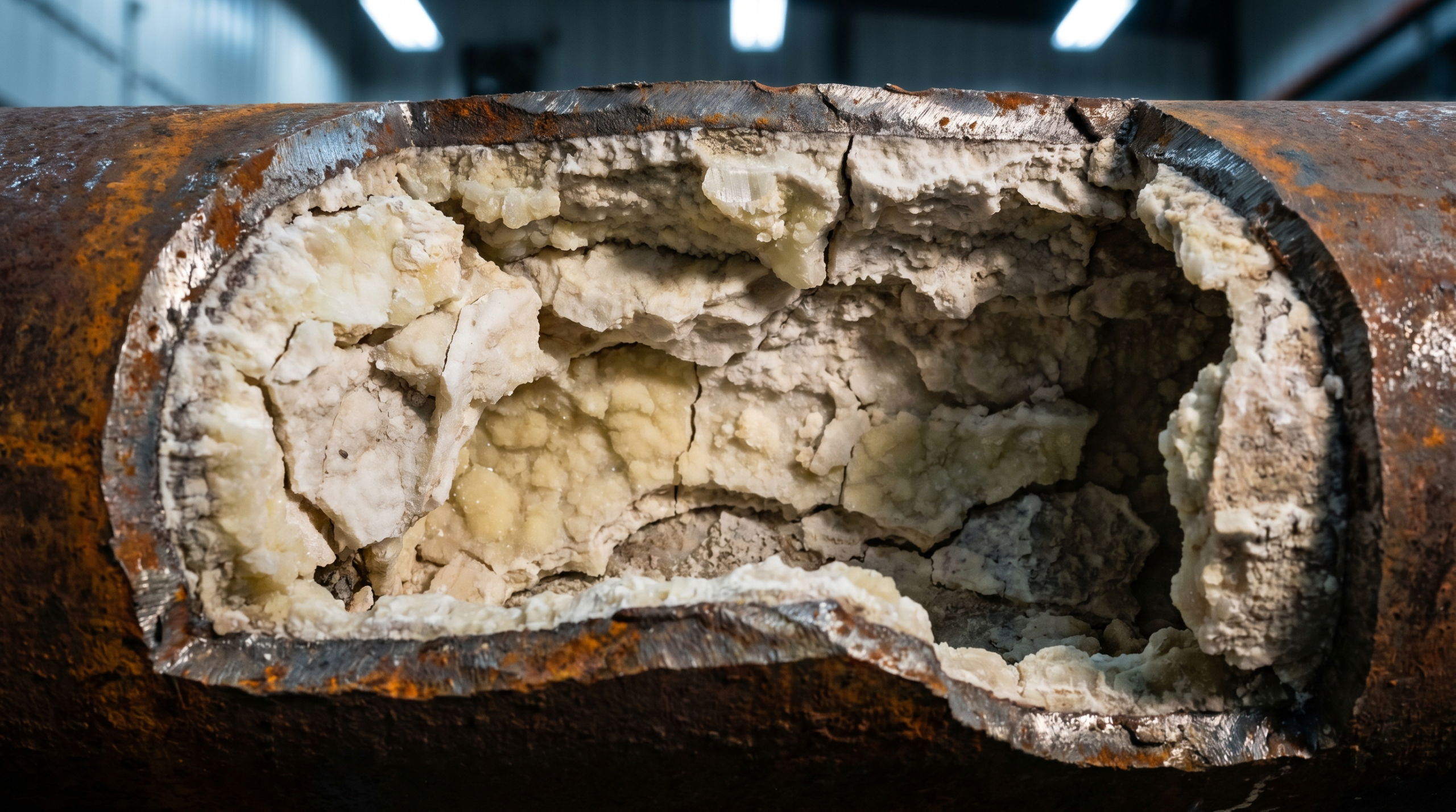
Calcium, magnesium, and silica – the usual suspects – drop right out of solution when the boiler water hits saturation limits. These hard, crusty deposits then coat your critical heat transfer surfaces: boiler tubes, heat exchanger walls, fire tubes. Here’s the kicker: scale acts like a super-insulator. Just a 1/32-inch layer of scale can increase fuel consumption by roughly 2%; at 1/4-inch, that figure rises to an 11% increase.[1] Many plant managers underestimate this energy waste. Beyond the efficiency hit, severe scale causes localized overheating of boiler tubes, often leading to tube failure, serious pressure vessel damage, and in the absolute worst cases, a catastrophic rupture. That’s a bad day for everyone.
Corrosion
Then there’s corrosion. Dissolved oxygen and carbon dioxide don’t just sit there; they actively attack boiler metal. Oxygen pitting, for instance, carves out small, deep craters in your boiler tubes and drum walls. Carbon dioxide dissolves in condensate return lines, forming carbonic acid – a corrosive solution that causes widespread thinning of return piping. Both these destructive mechanisms intensify dramatically when temperatures and pressures climb inside your system.
Recognizing these critical issues, authoritative bodies like the American Society of Mechanical Engineers (ASME) and the American Boiler Manufacturers Association (ABMA) have published clear feedwater quality guidelines for industrial boilers.[2][3] These aren’t just suggestions; they’re strict limits for parameters such as Total Dissolved Solids (TDS), hardness, iron, silica, dissolved oxygen, and pH. What we’ve observed over decades is that these limits become significantly tighter as boiler operating pressure climbs.
ASME/ABMA Boiler Feedwater Quality Limits
| Boiler Pressure | TDS Limit (ppm) | Hardness | Silica (ppm) | Iron (ppm) | pH Range |
|---|---|---|---|---|---|
| 0-300 psi (low pressure) | <3,500 | <0.3 gpg | <150 | <0.1 | 7.5-10.0 |
| 300-450 psi | <3,000 | <0.3 gpg | <90 | <0.05 | 7.5-10.0 |
| 450-600 psi | <2,500 | Trace | <40 | <0.03 | 8.0-10.0 |
| 600-900 psi | <1,500 | Trace | <30 | <0.025 | 8.5-10.0 |
| 900-1,200 psi (high pressure) | <1,000 | None detected | <20 | <0.02 | 9.0-10.0 |
| Above 1,200 psi (utility/power) | <150 | None detected | <2 | <0.01 | 9.0-10.0 |
Let’s put those numbers in perspective. Municipal tap water in most US markets typically comes in at 100-500 ppm TDS, with a hardness of 5-25 GPG – that’s 85-425 ppm as CaCO₃. As the table illustrates, this means average untreated tap water already fails to meet the feedwater quality requirements for practically every boiler except the very lowest-pressure units. The reality is that even low-pressure boilers, if fed untreated water, will accumulate scale rapidly. This practice inevitably leads to operational issues.
How Reverse Osmosis Fits Into Boiler Feedwater Treatment
This is where RO truly excels. A reverse osmosis system removes 95-99% of dissolved solids from feedwater before it ever reaches the boiler. Imagine a feedwater at 300 ppm TDS. After RO, the TDS level will be a mere 3-15 ppm – well within ASME limits, even for demanding medium-pressure boilers. This represents a massive improvement. Furthermore, notorious hardness-causing minerals like calcium and magnesium are effectively blocked by the RO membrane, completely eliminating the primary scale-forming ions.
Now, one crucial point: RO doesn’t remove dissolved gases like oxygen or CO₂. For these, downstream chemical or mechanical treatment is essential. Thus, the complete boiler feedwater treatment train for most industrial setups combines RO with robust deaeration and effective chemical oxygen scavenging.
Standard Boiler Feedwater Treatment Train
- Makeup water pre-treatment: This serves as the first line of defense.
- Sediment filtration (typically 5-25 microns) – crucial for protecting your sensitive RO membrane from any particulates.
- Carbon filtration – essential for removing chlorine and chloramine, which are notorious for degrading polyamide RO membranes.
- Water softener (sometimes optional for low-pressure systems) – this significantly extends RO membrane life by reducing scaling potential; it is essential for feedwater above 15 GPG hardness.
- 5-micron final pre-filter – a final layer of protection right before the water reaches the RO membrane itself.
- Reverse osmosis: The primary treatment stage. This step reduces TDS by a massive 95-99%, removing hardness minerals, silica, iron, and most dissolved organics. Product water (what is called permeate) is directed to the feedwater system; the reject (or concentrate) flows to drain, typically 15-30% of your initial feed flow.
- Deaerator or deaeration tower: This stage addresses dissolved gases. It mechanically strips out dissolved oxygen and CO₂ – either by heating the water or applying a vacuum. If the boiler runs above 150 psi, this is not optional; it is required. It reduces dissolved oxygen from a typical 8-10 ppm (at ambient conditions) down to a minuscule 0.007 ppm.[2]
- Chemical dosing: This stage fine-tunes water chemistry.
- Oxygen scavenger (like sodium sulfite or DEHA) – this scavenges any residual dissolved oxygen left after deaeration.
- Scale inhibitor – phosphate-based or polymer dispersants are used to manage any trace amounts of hardness that might remain.
- pH adjustment – absolutely vital for maintaining alkalinity in the optimal range of 8.5-10.0 pH, which actively suppresses corrosion.
- Condensate return monitoring: This step should not be overlooked. Return condensate absolutely needs to be tested for contamination before it is routed back into the feedwater system. Product leaks or process contamination in the condensate can introduce organics or acids that will wreak havoc on boilers. The potential risks make this step crucial.
RO System Sizing for Boiler Makeup Water
Boiler makeup water refers to replacing two fundamental losses. First, there is evaporation – the steam that exits the system as product or simply escapes. Second, there is blowdown – water intentionally drained to keep the TDS concentration in the boiler from becoming excessively high. Thus, accurately sizing an RO system involves calculating the total daily makeup demand.
Step 1: Calculate Boiler Steam Output
First, determine the boiler’s rated steam output. This is usually found in pounds per hour (lb/hr) or BTU/hr. Then, convert that figure into gallons per day (GPD) of evaporative loss. A quick rule of thumb is: 1 boiler horsepower (BHP) roughly equals 34.5 lb/hr of steam, which translates to about 4.1 GPD of makeup water.
Step 2: Add Blowdown Loss
Next, account for blowdown loss. The blowdown rate hinges on two factors: the feedwater TDS and the maximum allowable boiler water TDS (which is found in the ASME guidelines). Calculate ‘Cycles of Concentration’ (CoC) by dividing the Max boiler TDS by the Feedwater TDS. Once this is determined, blowdown as a percentage of the steam output is simply 100 divided by (CoC minus 1).
Consider a quick example. Assume RO permeate at a low 10 ppm TDS, and the boiler’s maximum allowable is 1,500 ppm TDS. This results in a CoC of 150. Thus, the blowdown amounts to a mere 0.67% of the total steam rate. This is incredibly low – and represents one of the biggest, often overlooked, advantages of RO pre-treatment. It dramatically reduces blowdown requirements, which in turn saves significantly on water and chemical costs. This is a significant advantage.
Step 3: Size the RO System
To size the RO system. The total makeup demand in GPD is the evaporative loss, plus the blowdown, plus an adequate 20-25% safety factor. This buffer is crucial for flexibility and peak demands. The RO system then needs to reliably produce that total volume within its available daily operating hours. For instance, if the boiler runs 16 hours a day but the RO unit can operate for 20 hours, the calculation is adjusted: RO capacity (GPD) = total makeup (GPD) multiplied by (16 divided by 20). Size the system to meet that number for optimal performance.
Example Calculation
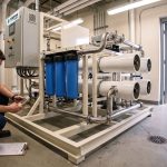
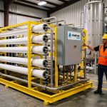
Consider a real-world example. Consider a 200-BHP fire tube boiler. That boiler produces roughly 820 GPD of steam. With the calculated blowdown at 0.67%, this only adds about 5.5 GPD. Thus, the total makeup amounts to around 826 GPD. Adding a practical 20% buffer, the requirement is 990 GPD. For this setup, a robust 1,000-1,200 GPD commercial RO system from AMPAC USA would easily handle the application, providing ample headroom even for occasional condensate losses.
RO vs. Softener-Only for Boiler Pre-Treatment
| Factor | Softener Only | RO Pre-Treatment |
|---|---|---|
| Hardness removal | Removes Ca/Mg (exchanges for Na) | Removes Ca/Mg and all other dissolved solids. |